Table of contents
- 1. Jan 2021
- 1.1. Tests in OCT_D mode
- 1.1.1. Monitoring FPGA temperature
- 1.1.2. Stability tests
- 1.1.3. Zero-baseline test
- 1.1.4. GComo
- 1.2. Tests in DDC_U mode
- 1.1. Tests in OCT_D mode
- 2. Jan 2020
- 3. Jan 2019
- 3.1. Overheating issue
- 3.2. GCoMo
- 3.3. 0-baseline Test
- 3.3.1. first run
- 3.3.2. second run
- 3.3.3. third run
- 4. 2017
- 4.1.1. 01.02.2017
- 4.1.2. 31.01.2017
- 4.1.3. 30.01.2017
- 4.1.4. 29.01.2017
- 4.1.5. 28.01.2017
- 4.1.6. 27.01.2017
- 4.1.7. 26.01.2017
- 4.1.8. 24.01.2017
- 4.1.9. 23.01.2017
- 4.1.10. 22.01.2017
- 4.1.11. 21.1.2017
- 4.1.12. 20.1.2017
Jan 2021
The DBBC3 has been returned from Bonn where it underwent a complete rehaul. The ADB3L and Core3H boards were replaced with the production version (v2). In addtion the following components were redone: cabeling, PC-board, FPGA heatsinks. The airvent grid has been removed in order to increase the airflow through the DBBC3.
Tests in OCT_D mode
Monitoring FPGA temperature
| T (before loading filters) | T (after loading filters) | |
|---|---|---|
| board A | 30 | 35.5 |
| board B | 30 | 36 |
| board C | 30 | 36 |
| board D | 31.5 | 38.5 |
Reworking the heatsinks and opening the airvents has significantly improved the cooling. Overheating issue from 2020 (see below) can be regarded as solved.
Stability tests
The testStabilityOCT.py was run continously over more than 3 days. In total 164 complete loops were executed of which 155 ran without error/warnings. In 9 cases no sampler phase synchronisation could be achieved during the startup procedure (5.5% failure). This is comparable to the results obtained in the Bonn lab. On the mid-term the synchronisation algorithms in the DBBC3 control software should be improved to eliminate these failures.
Zero-baseline test
A zero-baseline test was done using 5-9 GHz noise that was split to all 4 input IFs of the DBBC3 (with an additional line injected at 6048 GHz). Efficiencies were derived with zerocorr:
| recorder | correlation | efficiency | bit statistics | Plot |
|---|---|---|---|---|
| recorder1 | A0 - B0 | 80% | OK | PV_rec1.pdf |
| recorder2 | A2 - B2 | 86.2% | OK | PV_rec2.pdf |
| recorder3 | C0 - D0 | 84.6% | OK | PV_rec3.pdf |
| recorder4 | C2 - D2 | 86.4% | OK | PV_rec4.pdf |
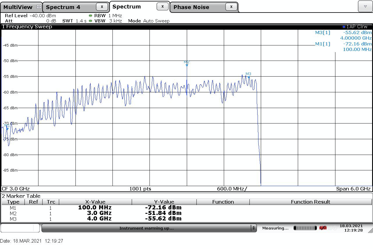
GComo
The output spectrum after the downconversion by the GComo:
Tests in DDC_U mode
TBD
Jan 2020
- The DBBC3 has been shipped back from Bonn to PV and has receivced an upgrade in the power distribution. First inspection shoed no transport damage the DDC_V and OCT_D modes start up normally with samplers and valons in lock.
Overheating issue
An airduct directly brings the cold air from the floor outlet to the DBBC3 frontside inlet. For OCT_D that is sufficient. Temperatures stay below 50°C without any additinal aitconditioning.
For the DDC_V mode the airduct is not sufficient. Temperarutes for board C around 55-56°C and can occasionally even reach 60°C. As a workaround an external airconditioning unit was connected to the frontside inlet of the DBBC3. That brings the temperatures down to around 50°C for board C. However the airconditioning unit cannot run permanently. On the midterm a heatpipe system for the DBBC3 is needed.
PPS jumps and sampler de-synchronization (DDC_V mode only?)
After the upgrade of the system in Bonn we see jumps in the internal vs. external PPS of about 2 microseconds after few minuites happening in the DDC_V mode. The jumps happen simulatenously with a loss of sampler sync on all 4 boards. The following tests were done:
- testing other modes: in DDC_L and OCT_D no PPS jumps and loss of sampler sync occur. Power consumption and board temperatures are comparable to DDC_V mode.
- running V1 DDC_V firmware on the Bonn system shows no PPS jumps/sampler sync problems.
- running V2 DDC_V firmware on the PV systems shows no PPS jumps/sampler sync problems.
Update (5.3.2020): In DDC_V mode the issue comes and goes with reloading of the firmware. After reloading the firmware the monitorDDC.py script was run for a longer duration. If jumps occured (typically within the first hour), the firmware was reloaded and the test was repeated. In several cases no jumps occured even after 24hours.
Conclusions:
- The effect is transient and depends on can appear after loading the firmware. If it does not happen within the first hour or so the system seems to be stable.
- The effect is not heat related; it also occurs when external air conditioning is used.
- The loss of sampler sync does not occur in the OCT_D mode.
Jan 2019
After a major rehaul of the hard and software the DBBC3 system was shipped back to PV.First inspection indicated that no damage
was done during transport. After power up all systems seem to work as expected.
Overheating issue
After loading the tap filters in the OCT mode temperatures on the Core boards were observed to rise significantly (typically by 4-5 deg). Letting the system run over night caused failure. As a counter-measure the top cover was removed an a fan unit with 3 fans (two front one back side) was installed. Also an additional cooling vent was installed on the floor in front of the rack that hosts the DBBC3. This was sufficient to prevent failure even over a few hours of operations. However removing the fan unit in order to do maintenance caused system failure after a few seconds. The DBBC3 was therefore removed from the top position in the rack and was moved to the very bottom just in front of the floor vent. This has lowered the temperature at the air intake by another 4 degrees. Salvador also reworked the lid fan unit. It now hosts 4 fans with higher capacity: threee directly above the core boards and one directly over the GCOMO units. Monitoring with ChipScope shows the FPGA temperatures not to increase above 57 degrees even when continously running the tap filters on all 4 boards:
A: 53 deg
B: 55.5 deg
C: 57 deg
D: 53.5 deg
TODO: check with Gino./Michael if the distance between core boards can be increased.
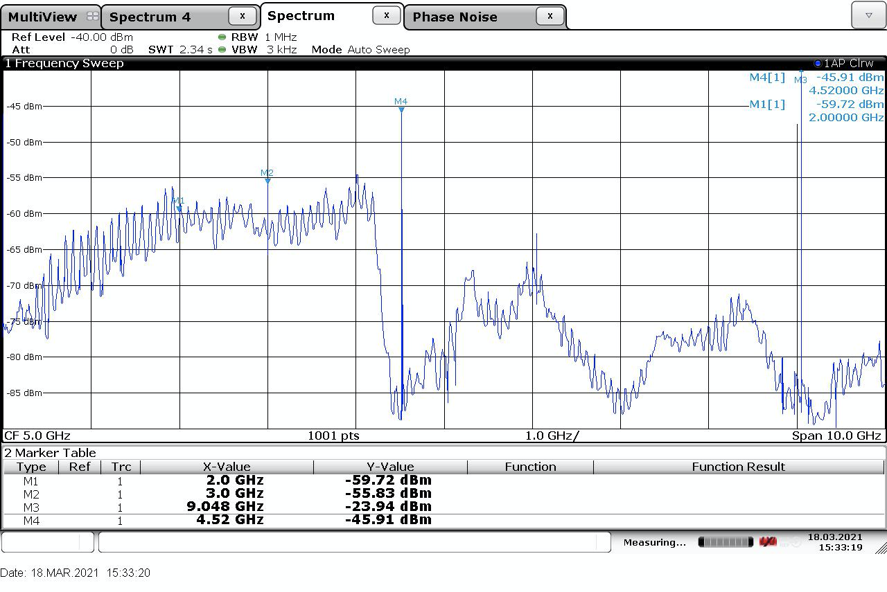
GCoMo
The noise source was connected to all 4 inputs of the DBBC3. The outputs after the GCOMOs were tapped off and put on a spectrum analyzer.
| IFs inputs | spectra after GCoMo |
|---|---|
| IF A | 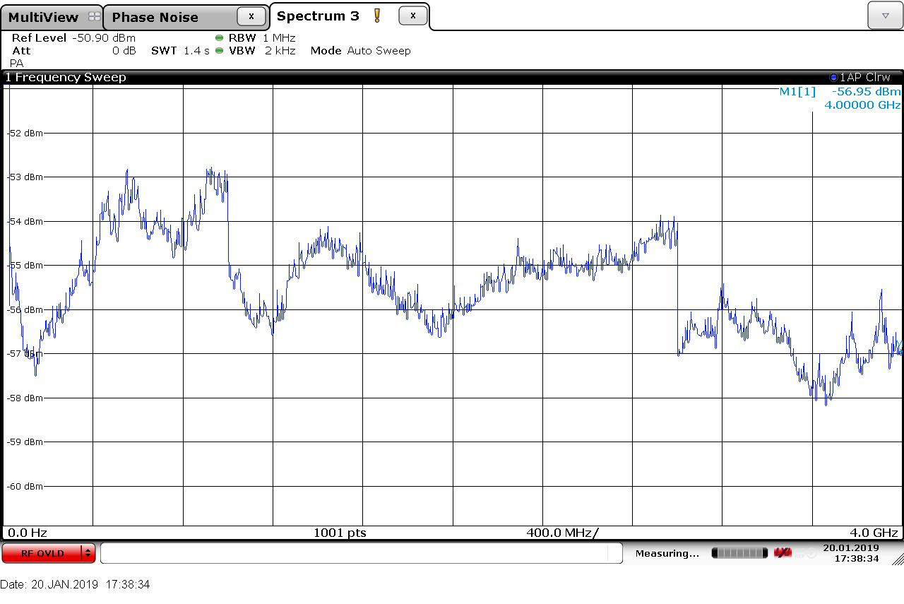 |
| IF B | 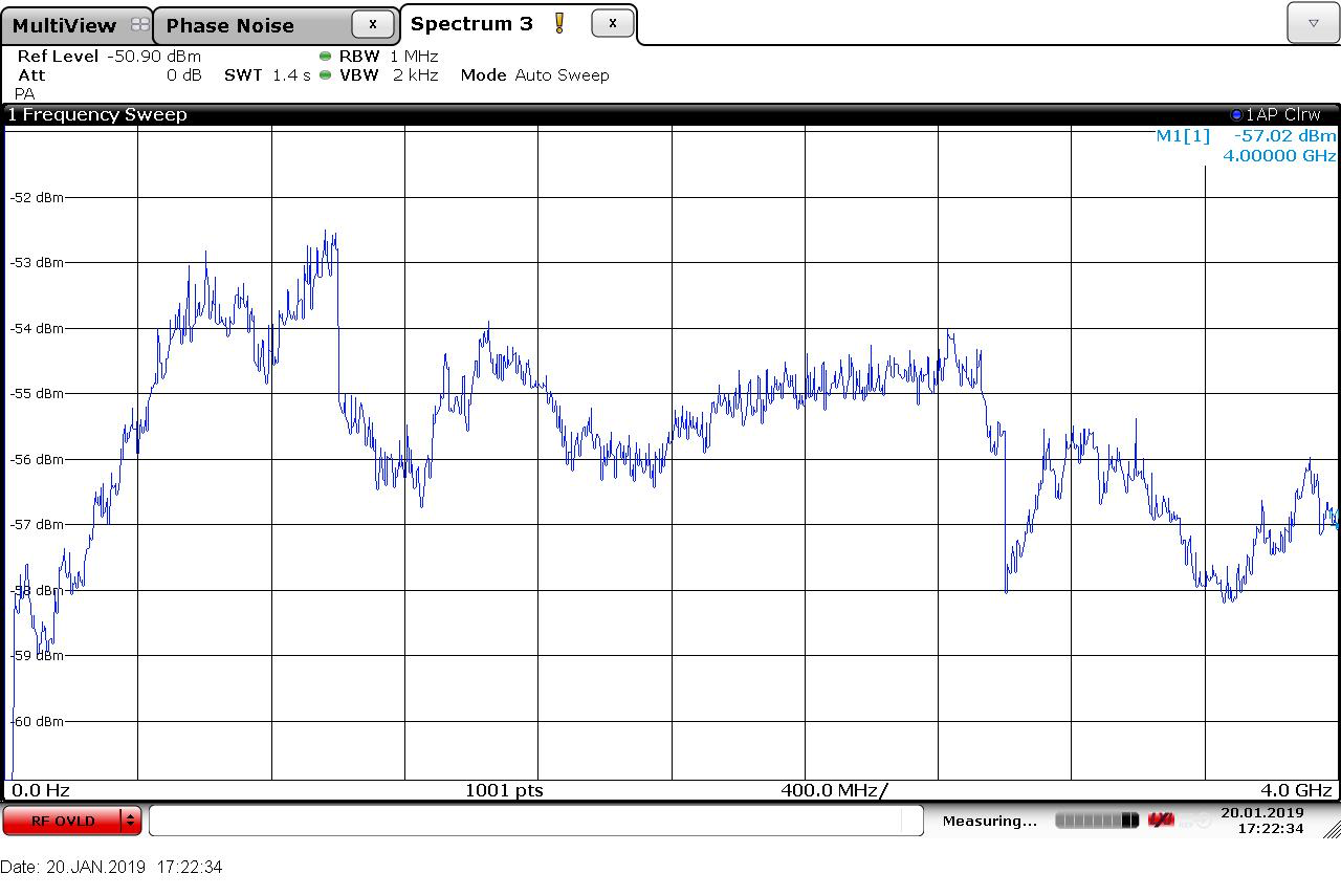 |
| IF C | 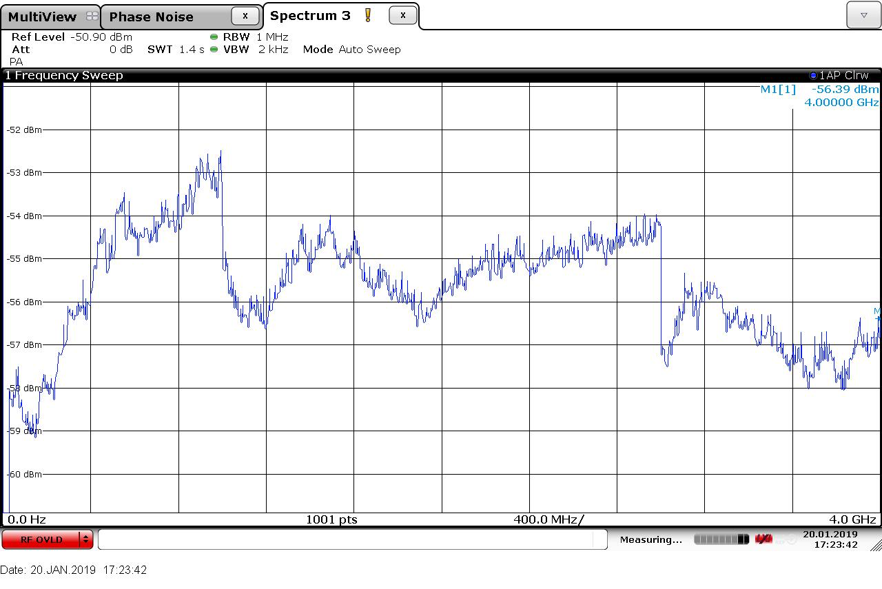 |
| IF D | 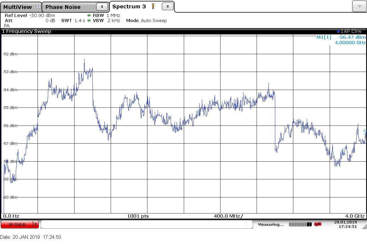 |
0-baseline Test
setup:
Telescope was parked with IFs (230 GHz) on ambient load. IF1 (USB LCP) was attached to board A and filtered 5-9GHz. The downconverted output (after passing through a lowpass filter 0-4 Ghz) was fed to a 4-way spltter and hte ouputs were connected to all 4 inputs (A,B,C,D) of the DBBC3.
The used low pass filter was of poor quality. Approx. the last 400 MHz are attenuated significantly.
firnware: OCT D V110
For details of the initialization & verification see: initABCD.txt
Recording scheme
| input | tap1 | tap2 |
|---|---|---|
| A | recorder1: 12 | recorder2 : 12 |
| B | recorder1: 34 | recorder2: 34 |
| C | recorder3:12 | recorder4: 12 |
| D | recorder3:34 | recorder4:34 |
correlation:
data was recorded via a schedule simultaneously on all 4 recorders. Chunks of 1GB were extracted and transferred to Bonn. Correlation was done in /Exps/TESTS/PV_jan2019_zbt/dbbc3
first run
tap1: 2000-4000_floating.flt
tap2: 0-2000_floating.flt
| job | baseline | HOPS | Efficiency |
|---|---|---|---|
| ABLow | A1 -B1 | 1200 | 78% |
| ABHi | A2 -B2 | 1211 | 80% |
| ACLow | A1 -C1 | 1300 | 73% |
| ACHi | A2 -C2 | 1311 | 65% |
| ADlow | A1 - D1 | 1400 | 73% |
| ADHi: | A2 - D2 | 1411 | 80% |
| BCLow | B1 - C1 | 2300 | 75% |
| BCHi | B2 - C2 | 2311 | 80% |
| BDLow | B1 - D1 | 2400 | 84% |
| BDHi | B2 - D2 | 2411 | 81% |
| CDLow | C1 - D1 | 3400 | 77% |
| CDHi | C2 - D2 | 3411 | 77% |
second run
tap1: 0-2000_floating.flt
tap2: 0-2000_floating.flt
| job | baseline | HOPS | Efficiency |
|---|---|---|---|
| AALow | A1 -A2 | 1100 | 83% |
| BBLow | B1 -B2 | 2200 | 82% |
| CCLow | C1 -C2 | 3300 | 83% |
| DDLow | D1 -D2 | 4400 | 89% |
third run
tap1: 2000-4000_floating.flt
tap2: 2000-4000_floating.flt
| job | baseline | HOPS | Efficiency |
|---|---|---|---|
| AAHi | A1 -A2 | 1111 | 87% |
| BBHi | B1 -B2 | 2211 | 87% |
| CCHi | C1 -C2 | 3311 | 88% |
| DDHi | D1 -D2 | 4411 | 88% |
2017
01.02.2017
Mounted Front Cover and new Top Cover with Fans provided by Salvador, will let it run over night to see if still overheating with covers.
Cleaned up harddrive to remove old and unused files.
31.01.2017
Second Observation run with new Control Software version. No more drift from individual sampler power levels.
30.01.2017
Changed Control Software to remove oscillation in AGC Control, so that fine adjustment of offset and gain on Core3H can be activated.
Prepared DBBC3 with this new configuration.
29.01.2017
First Observation run, no problems with DBBC3 despite small drifts in power levels.
28.01.2017
Prepared DBBC3 for Observation starting 29 th at 2:30. No Problems, only small drift in power levels of two samplers.
27.01.2017
DBBC3: Checked the stats of DBBC3 after letting it run over night with covers mounted, it lost synchronization in the first sampler of the first module. After resetting samplers it immediately lost synchronization again. Removed covers and let it cool down for 30 minutes. With covers removed DBBC3 was running stable for the whole day.
Recalibrated DBBC3 with ambient load from antenna as noise, powerlevel and stats from samplers had very good values.
26.01.2017
24.01.2017
DBBC3: Made Zero-Baseline Tests with modules 1 and 2, including down-conversion (6 GHz tone injected).
23.01.2017
DBBC3: Further testing and recording, made some modifications to the control software to improve calibration accuracy and speed.
22.01.2017
DBBC3: After reattaching the SMA connector to IFA 0-4 GHz input, the connector on the GCoMo side got loose,.This caused an SMA cable in the GCoMo to get ripped of. We were able to find a replacement cable and repair the GCoMo. We replaced the snap-rings to prevent further loosening of the connectors.
Tested modules 3 and 4, found that sampler 2 of module 3 is hanging, sending only FFFs to the Core3H. This was not the case in the lab in Bonn, suspected that the connectors got damaged during transport or reassembling. Checked the 140-pin connectors under the microscope, some of the pins have almost no soldering. Since modules 1, 2 and 4 are working fine and only two modules are needed for run in April, we dediced to leave it that way until after the run.
21.1.2017
Mark6 ethernet: pv-mark6-1 lost 10G network connection occasionally. Inspection showed that this is only affecting the two ethernet ports of the card being close to the chassis edge. This is very likely due to the transceivers becoming critically hot due to bad airflow within the mark6 chassis. As a workaround the transceivers were placed into pv-mark6-3 as it is closer to the floor with lower ambient air temperature. The mark6 machines were taken from the rack and the network cards were rearranged (closer to the middle and leaving a one-slot gap between them).
Mark6 installation: installation of the 2015 version of the mark6 software was finished on pv-mark6-3 and pv-mark6-4. The system time was set to UTC and the proper NTP functionality was verified. On pv-mark6-4 a problem occured when trying to open a group (permission problem on /mnt/disk/?/? tree). Deleting the /mnt/disks tree and recreating it by hand has solved the problem.
DBBC3: Testing of DBBC3 was continued with recordings on mark6. Recording only works if correct MAC-Addresses are set in Core3H-Config-Files. Recording was done with noise and 4.5 GHz line, to test down-conversion, which is working as expected.
20.1.2017
DBBC3:
- Unpacked and reassembled DBBC3, no visible damage
- One of the fibre cables for connecting the mark6 turned out to be defective. Used the fibre of the DBBC2 FiLA10G board as a temporary replacement.
- Installation and first testing of DBBC3:
- The powerlevel of 10 MHz had to be adjusted (should be between 0 and 3 dBm)
- recalibration: levels of gain, offset and delay were as expected, only small adjustments necessary
- connected 2-18 GHz noise source on 4-8 GHz input of IF A and IF B, we had to use 3 dBm attenuators on input to get power levels in good range for DBBC3:
- agc target value 28000
- results in attenuation 15 to 16 dBm in GCoMo with agc on.
- GPS timesync working fine
.JPG)


.JPG?size=webview "Noise_source_5to9 (1).JPG")


Comments