Table of contents
- 1. Clock synthesizer
- 2. R2DBE
Clock synthesizer
Unit was installed with the 10MHz connected from the Maser Reference Distribution box located in the VLBI rack. The power of 10 MHz input signal was attenuated to 3.5 dBm.
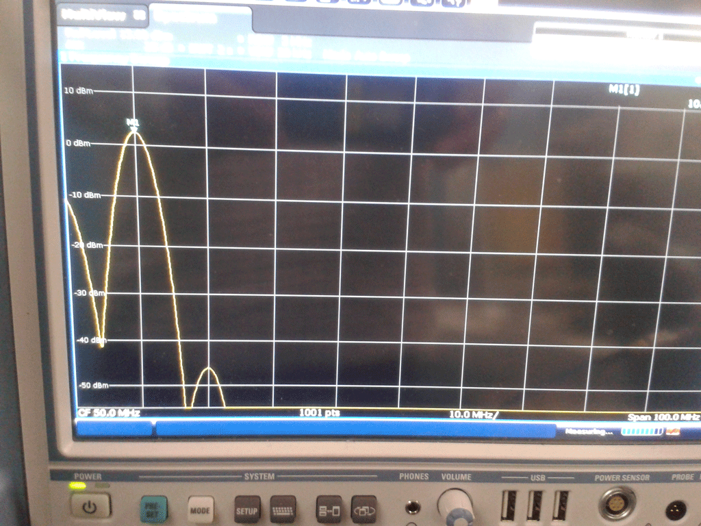
The output signal was inspected on the spectrum analyzer. The line was located at exactly 2048 MHz. The level on output pin 0 was attenuated by 3dB. The resulting peak output levels were:
Pin 0: +4.14 dBm (to r2dbe-1)
Pin 1: +4.00 dBm (to r2dbe-2)
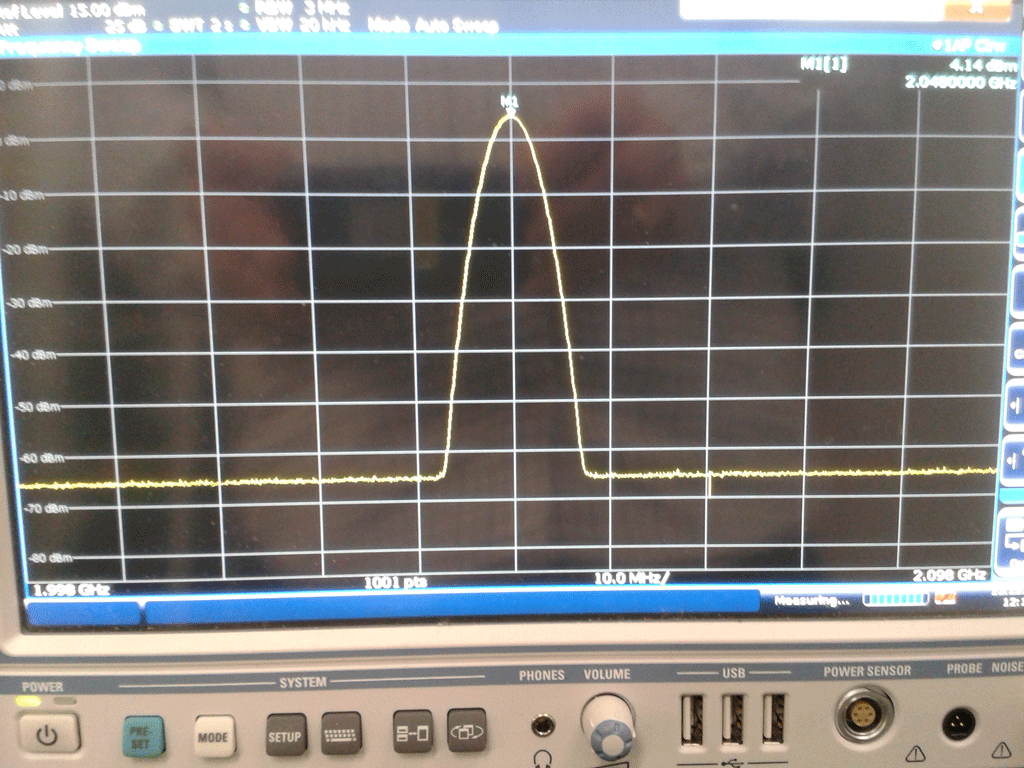 | 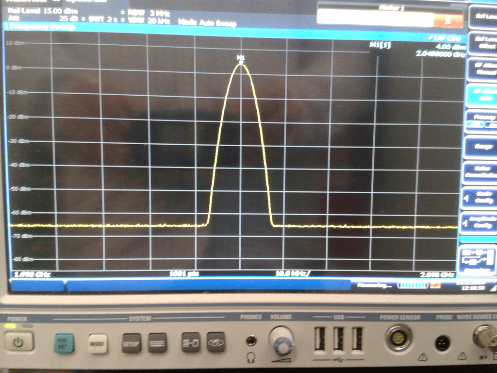 |
| Pin 0: Output Signal | Pin 1: Output Signal |
R2DBE
Installed both R2DBE units. Connected clock to the front side pins. Connected 1PPS to the distributor box in the VLBI rack. Network cables connected to the network hub serving 192.168.178.X. Booted pv-mark6-1 and connected its second network interface with the network hub.Then started up the R2DBEs. Boot succesful with the following hostnames/IPs:
r2dbe-1: 192.168.178.60
r2dbe-2: 192.168.178.61
Both R2DBEs can be reached via ssh from pv-mark6-1 (user root).