Table of contents
- 1. General
- 2. DBBC2
- 2.1.1. Firmware
- 2.1.2. Tone injection
- 3. DBBC3
- 3.1.1. Firmware installation
- 3.1.2. IF-Setup
- 3.1.3. System verification
- 3.1.4. Tone injection
- 3.1.5. Recording
General
1st LO = 92100 MHz
Total LO (DBBC2) = 85500 MHz
Total LO (DBBC3) = 84100 MHz (UI band)
DBBC2
Firmware
-
Installed new firmware ddc v107 beta3
-
Finished DBBC3 calibration
Tone injection
- noise + tone injected into pins 4 of board A and B
- verified if power levels (attenuation 23)
- set vsi_clk=128
- set dbbcform=astro
| tone (MHz) | IF A | IFB | |
|---|---|---|---|
| 528 | OK | OK | |
| 592 | OK | OK | |
| 656 | Missing | OK | |
| 720 | OK | OK | |
| 784 | Missing | OK | |
| 848 | OK | OK | |
| 912 | Missing | OK | |
| 976 | OK | OK |
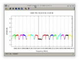
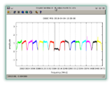
Bandpass plot shows that LSB of BBC2, BBC3, BBC4 are corrupted
Cleaned connectors of VSI1 cable connectin DDBC2 to Fila10G. No change. As a test have re-configured Fila10G to use vsi2 instead of vsi1 which has not changed the result. This implies that it is not a transmission problem over the VSI cables.
Update: Due to a power failure on March 3rd the VLBI equipment was brought down (DBBC2, Fila10G). After restarting all equipment the bandpass now looks good and lines are verified in all subbands.
DBBC3
Firmware installation
- installed DDC_V_123
IF-Setup
IF1 (E0VLI, LCP) => CoreBoardA => recorder2 eth3 => Module MPI%8005 (slot 1)
IF3 (E0HLI, RCP) => CoreBoardB => recorder2 eth35 => Module MPI%8008 (slot 2)
System verification
- run setupDBBC3_DDC_V.py
Tone injection
Tone was injected into the beam at 86.242GHz
Line appeared in both polarizations in the baseband at 3190 MHz.


